
How to Switch 2 Key Cards on Multiple Switches: Full Guide
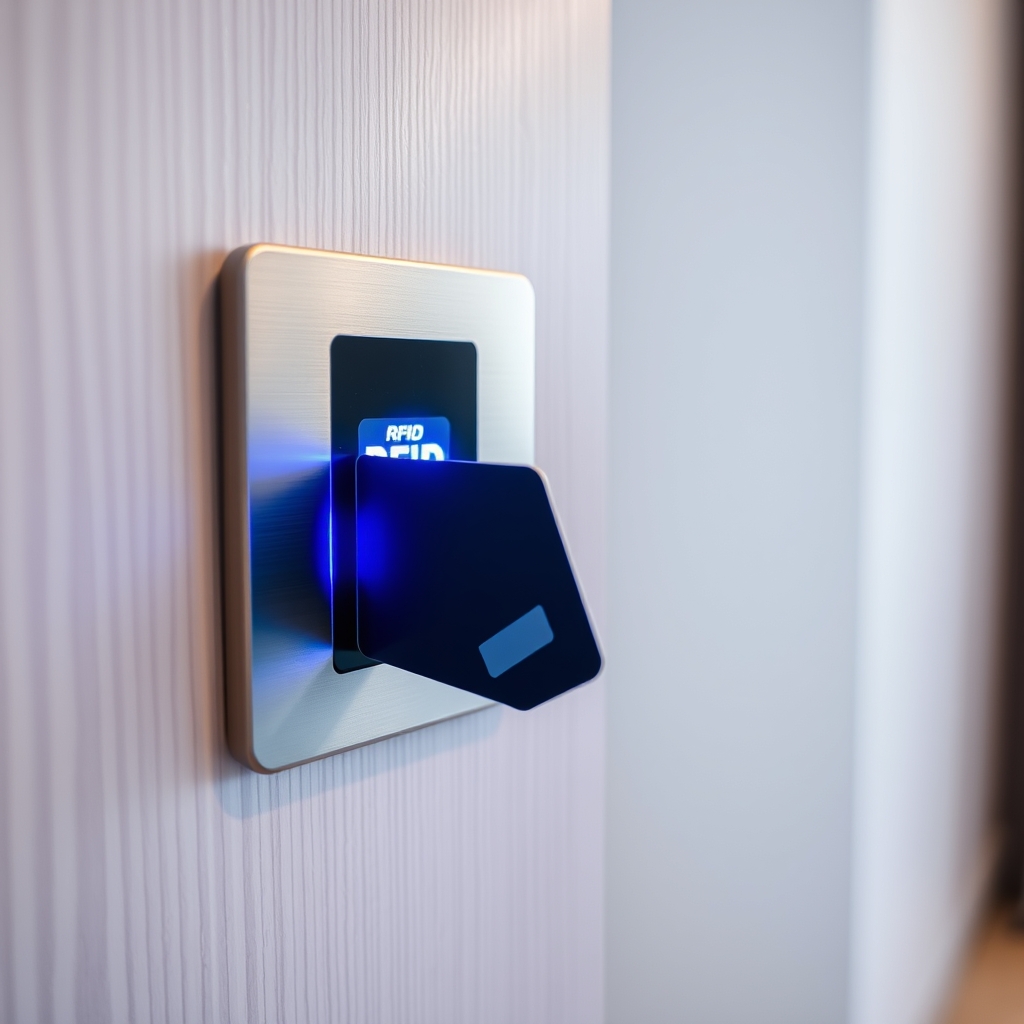
Managing access control and electrical power distribution in commercial facilities, hotels, and modern residential properties often requires flexible card key configurations. When you need to operate multiple electrical switch units or power saver sockets using a primary and secondary card, setting up the hardware correctly saves hours of frustrating troubleshooting.
Whether you are managing a short-term rental or configuring multi-room power relays, understanding how to switch 2 key card on multiple switches ensures reliable operation without electrical overloads.
This guide breaks down the underlying technology, programming sequences, wiring diagrams, and troubleshooting techniques required to configure dual key cards across multiple keycard wall switches.
Understanding Key Card Switch Technology and Dual-Card Functionality
Key card switches act as primary power gates or access authorization points. When a user inserts an authorized card into the slot, an internal micro-relay closes, sending electrical power to lighting, HVAC units, or secondary control modules.
Mechanical vs. High-Frequency RFID Card Switches
Older card switches relied on mechanical microswitches triggered by physical card dimension alone. Modern installations utilize radio frequency identification (RFID) or magnetic strip readers.
- Mechanical Switches: Activated by any object shaped like a standard credit card. They offer no security or identity verification.
- Low-Frequency RFID (125 kHz): Simple read-only proximity chips. Easy to pair across multiple switches, but offers minimal encryption.
- High-Frequency RFID (13.56 MHz / ISO 14443): Smart card technology capable of holding encrypted sector data. These switches verify unique card IDs (UIDs) or sector keys before closing the internal contactor.
How Multi-Card Master and Guest Logic Operates
To allow two separate key cards (for instance, a primary guest card and a secondary housekeeping/maintenance card) to activate multiple switches throughout a facility, the internal memory of each switch unit must store both unique card identifiers.
When you attempt to switch 2 key card on multiple switches across different power zones, frequency alignment between the RFID reader and the keycard chipset is paramount. If one switch operates on a 13.56 MHz Mifare protocol and another uses a 125 kHz EM4100 chip, a single keycard set cannot function across both units.
Step-by-Step Guide to Program and Switch 2 Key Cards on Multiple Switches
Follow these steps to program your system when you need to switch 2 key card on multiple switches without resetting existing user permissions or causing synchronization errors.
Step 1: Verify Key Card Frequency and Encryption
Before programming, confirm that both key cards use identical chip protocols. Check the specs on your keycard readers or test them with an RFID analyzer. Standard international standards like ISO/IEC 14443 govern high-frequency contactless smart cards, ensuring compatibility across compliant reader hardware.
Step 2: Clearing Legacy Memory on Target Wall Switches
If the wall switches were previously paired with older key cards, wipe their memory banks to avoid memory capacity limits:
- Isolate main breaker power to the target switches for 10 seconds, then restore power.
- Hold down the manual override button (or insert a dedicated system reset card) on the faceplate for 8–10 seconds until the LED status indicator flashes rapidly.
- Release the button. The switch is now in open programming mode.
Step 3: Enrolling Card 1 and Card 2 across Wall Units
To configure two cards across all switches:
- Put Switch A into Pairing Mode (typically indicated by a slow-flashing blue or green LED).
- Insert Card 1 into Switch A. Wait for a confirmation beep or solid LED light.
- Remove Card 1 and immediately insert Card 2 within 5 seconds. The switch will store both UIDs in its internal EEPROM memory.
- Repeat this exact sequence on Switch B, Switch C, and any remaining hardware units.
Step 4: Testing Relay Delay and Multi-Zone Cutoffs
Most key card power switches feature a built-in off-delay timer (typically 10 to 30 seconds) to allow guests to exit safely after removing their card. Insert Card 1 into Switch A and check power output. Remove Card 1, verify the delay countdown, then test Card 2 on Switch B to confirm multi-card validation.
Wiring Configurations for Controlling Multiple Switches with Two Key Cards
How your key card units are wired electrically dictates whether a single inserted card can energize one room zone or multiple sub-panels simultaneously.
Direct Line Voltage Multi-Switch Control
In direct line-voltage setups, 120V/230V AC current passes directly through the key card unit's internal switch contacts.
- Single-Phase Parallel Wiring: Connect the live input feed to all key card switches in parallel. The switched load outputs remain isolated to individual lighting or power circuits.
- Neutral Wire Integrity: Electricians often encounter relay chatter when trying to switch 2 key card on multiple switches on shared neutral wire circuits. Ensure each switch unit has a dedicated neutral return wire to prevent voltage drop and memory corruption during relay activation.
Low-Voltage Contactor and Relay Bus Systems
For larger multi-room layouts or heavy inductive loads like air conditioners, key card switches should not switch main line power directly. Instead, connect the key card switches to low-voltage relay contactors or a central smart building controller.
Using low-voltage (12V–24V DC) control signals allows multiple key card switches to trigger a single central power contactor without risking electrical arc damage across keycard terminal blocks. Always adhere to local electrical standards such as NFPA 70 (National Electrical Code) when wiring low-voltage control circuits alongside main power feeders.
Troubleshooting Common Issues in Multi-Switch Key Card Environments
When managing dual key cards across multiple switches, technical glitches can occasionally occur. Here are solutions to the most common setup errors:
Key Card Recognition Delays and Signal Interference
If a key card works on Switch A but requires multiple attempts on Switch B, electromagnetic interference (EMI) may be affecting the antenna coil inside the switch faceplate. Ensure high-voltage AC cables are kept at least 2 inches away from low-voltage RFID sensor wires.
Neutral Wire Voltage Drops and Ghosting
If the LED backlight on your key card switch flickers continuously when no card is inserted, stray capacitive coupling is likely present. Installing a small RC snubber resistor across the switched load terminals neutralizes stray voltage spikes.
Overwriting Master Cards during Re-enrollment
When enrolling Card 2, ensure you do not inadvertently trigger a hard reset on the switch memory. If you leave Card 1 out of the slot for longer than 10 seconds during programming mode, some switch brands will automatically close the programming window and overwrite previous entries.
By following correct wiring and programming protocols, you can smoothly switch 2 key card on multiple switches across your entire property portfolio.
Key Card Switch Hardware Comparison
Frequently Asked Questions
Can I use any standard RFID card to switch multiple key card units?
No. The RFID cards must match the operating frequency (125 kHz vs 13.56 MHz) and communication protocol supported by your key card switches. Standard credit cards or unformatted chips will not activate encrypted smart card switches.
How many key cards can be paired to a single wall switch?
Most entry-level RFID key card switches can store 2 to 5 card IDs in their local memory. Commercial-grade smart switches linked to a central management controller can recognize thousands of unique key cards across an entire building network.
What happens to paired key cards if power is lost?
Key card switches utilize non-volatile EEPROM memory to store card credentials. Paired card data and programming settings remain intact even during extended electrical blackouts or power outages.
Why does my switch remain powered on after removing the key card?
Most hospitality card key switches feature an intentional off-delay timer (usually 15 to 30 seconds). This allows occupants time to pull their key card, exit the room, and close the door before interior lights shut off completely.
Related Articles
 Gaming
How to Check If Your Laptop Can Run Any Game (Step-by-Step)
September 3, 2026 Gaming
Is Google Play Games on PC Laggy? Causes and Quick Fixes
September 3, 2026 Gaming